Lab Projects
Many of my electrical and computer engineering courses include hands-on lab work. I’ve learned a lot about lab-bench test setups, programming, FPGA, and circuit design.
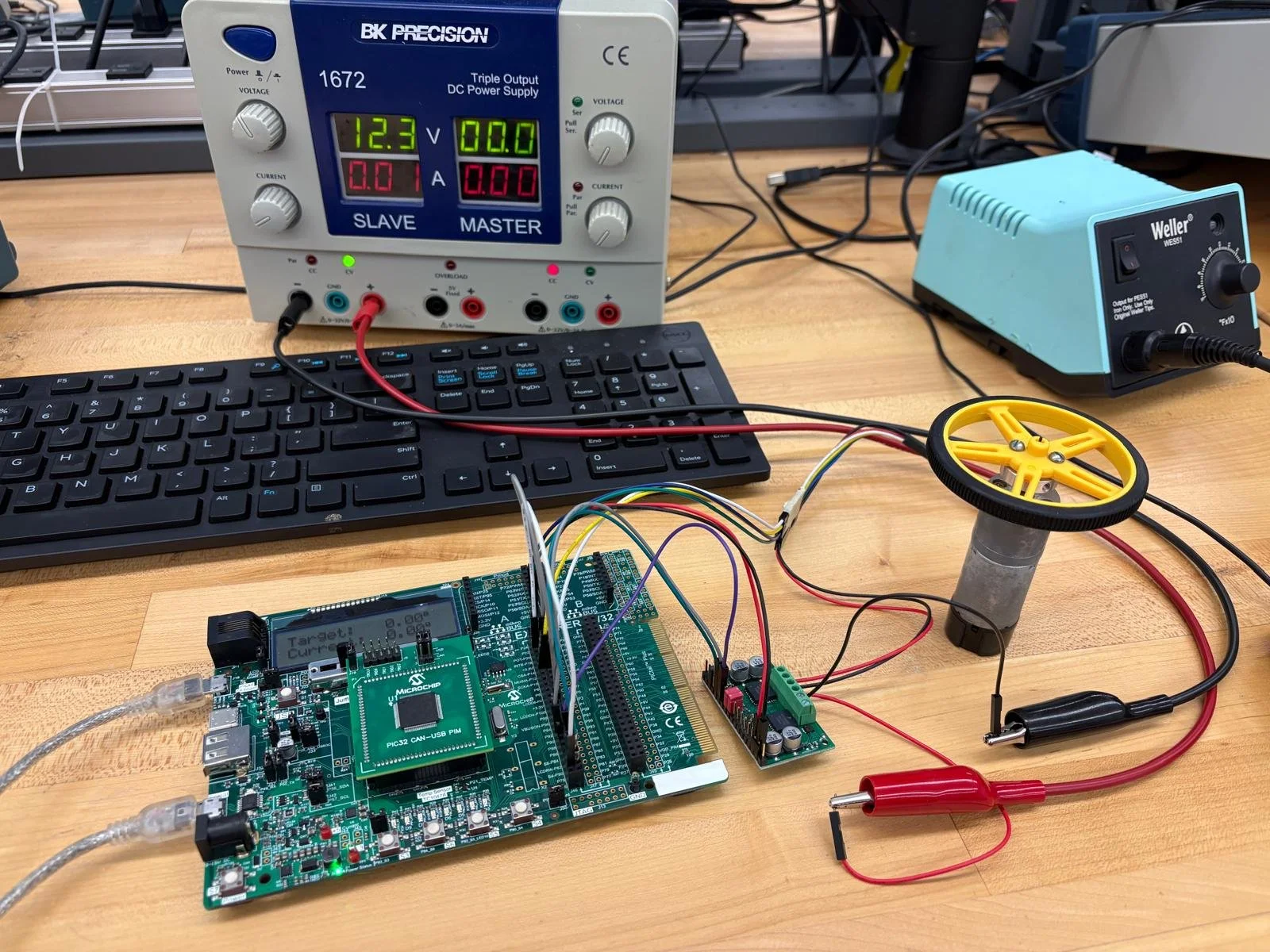
PID motor controller and UART
This project used a PIC32 microcontroller, explorer board, metal gearmotor with encoder, and H-bridge motor driver. The I wrote code in C to do the following:
Receive a reference angle from a MATLAB script via UART
Control the motor to move to the reference angle using three different methods, including integral-proportional mode.
Continuously update the LCD screen with the current and reference angles
Use UART to send angles to MATLAB and create a plot over 5 seconds.
This project included designing an integral-proportional motor control procedure, UART communication, wiring multiple devices, and programming a microcontroller (interrupts, internal timers, tri-state register assignments, output compare, and an LCD display driver).
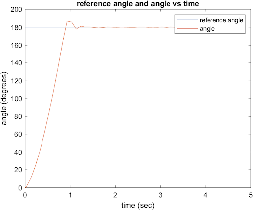
underdamped
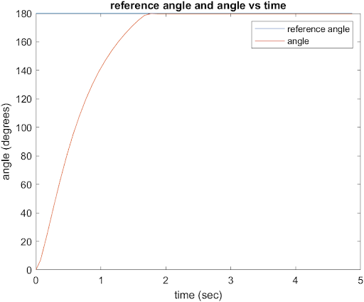
critically damped
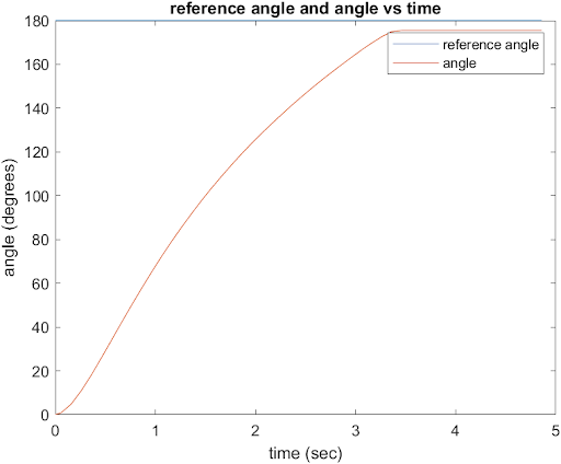
underdamped
Digital Logic Labs
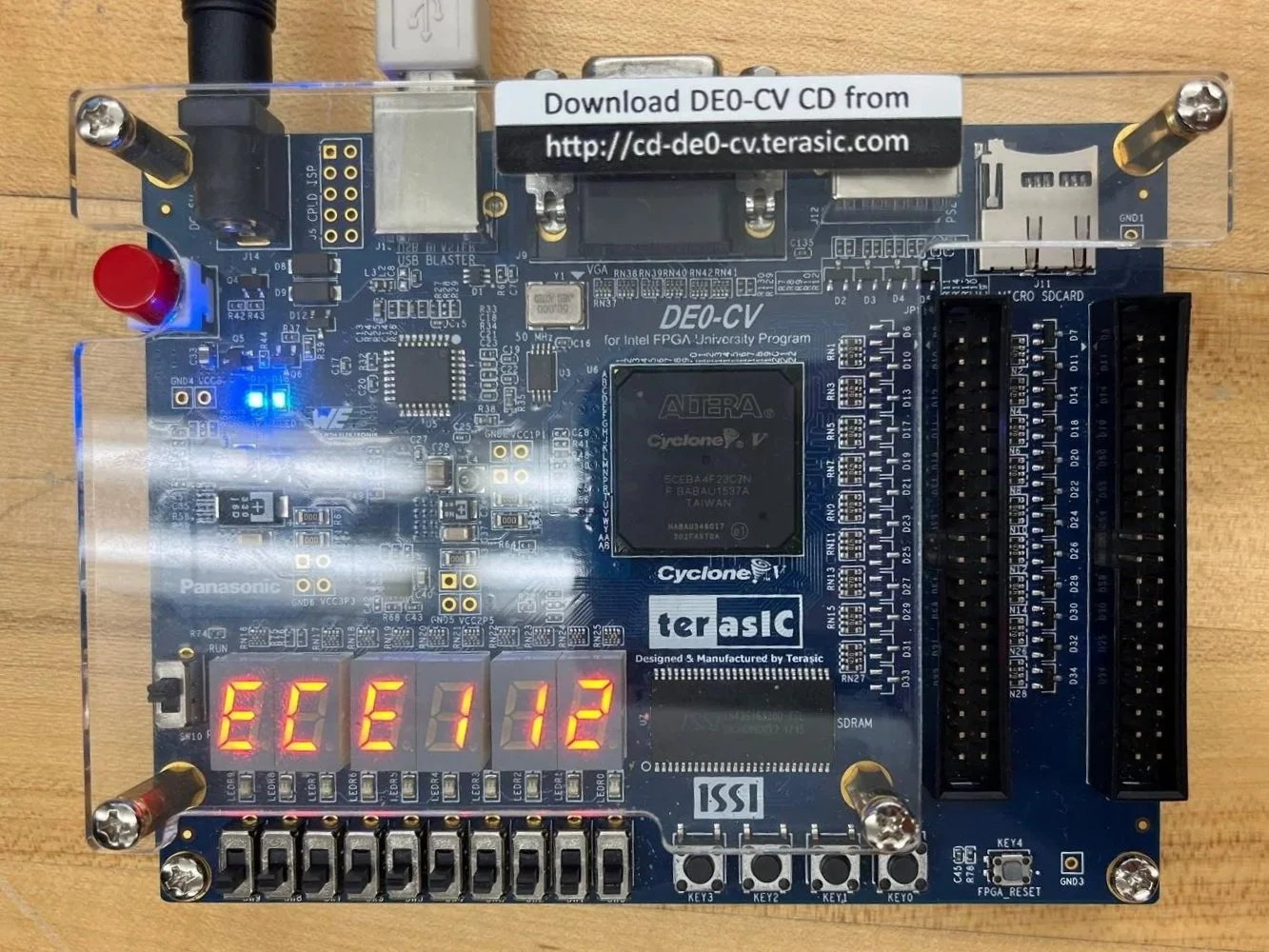
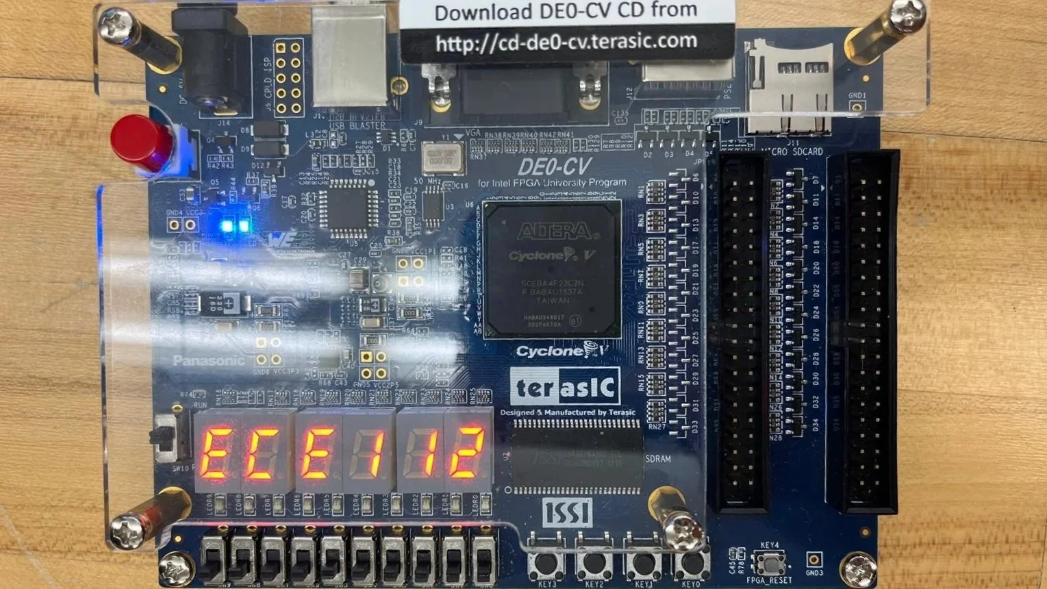
The two projects below were selected from a total of 10 labs from my Logic Design class and completed with two other classmates. Each was implemented on the DE0-CV programmable logic board (right).

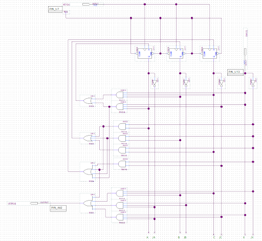
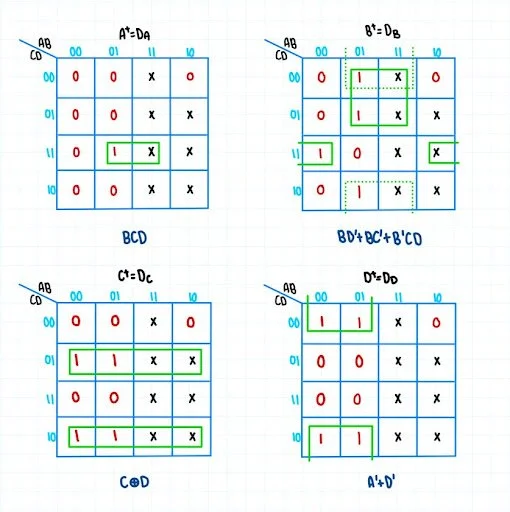
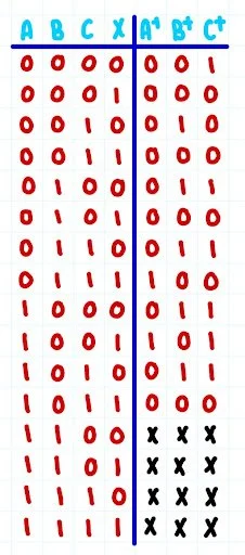
Counter with Flip Flops: We created an optimized click counter using the minimum number of devices. We used a truth table (left) and Karnaugh Maps (middle) to design out logic circuit and then implement with D flip-flops (right).
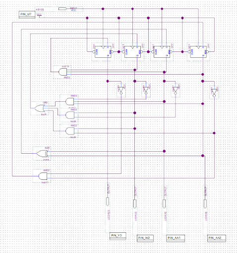

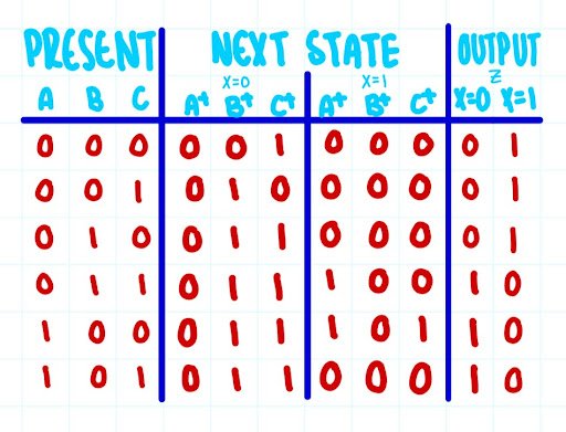
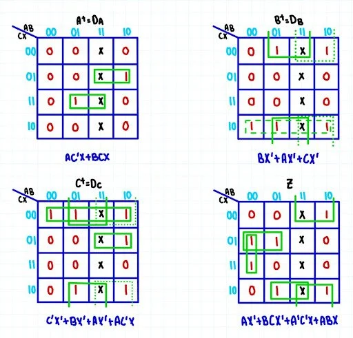
Mealy Machine: The output equals the input until 000 input is identified. Then, the output equals the inverted input until a 111 input is identified. Then the output equals the input again. We started by creating a state map (top left), state table (top middle), truth table (bottom left), Karnaugh Maps (bottom middle). Then we used D flip flops to design a Mealy Machine (right).